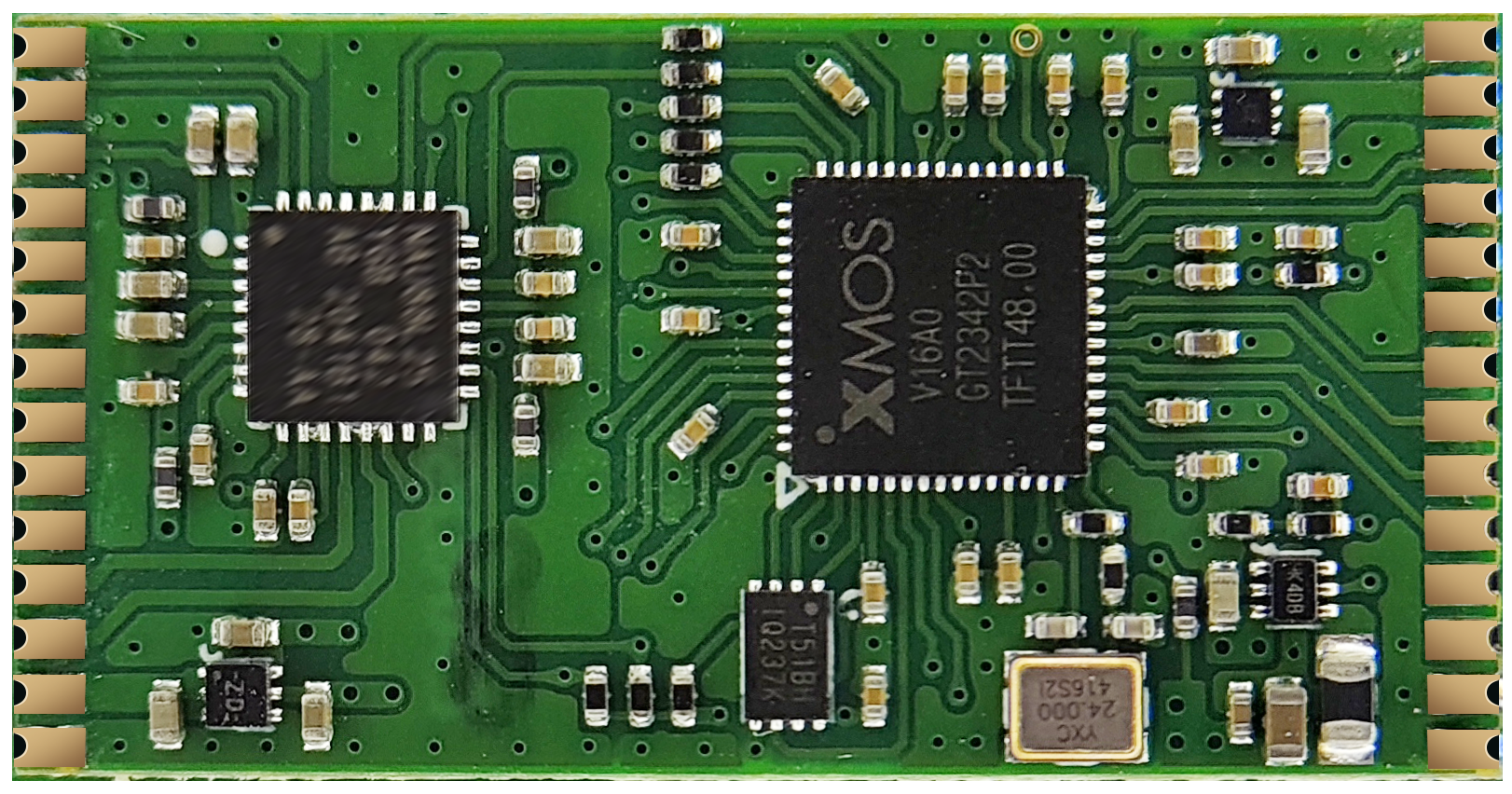
A316-Codec-V1
XMOS XU316 Module with Integrated Codec for Microphone Applications
1. Product Introduction
1.1 Product Description
- A316-Codec-V1 is a module specifically designed for USB microphone applications, integrating the XMOS XU316 processor and the 88L21 high-performance audio codec, delivering exceptional audio processing performance.
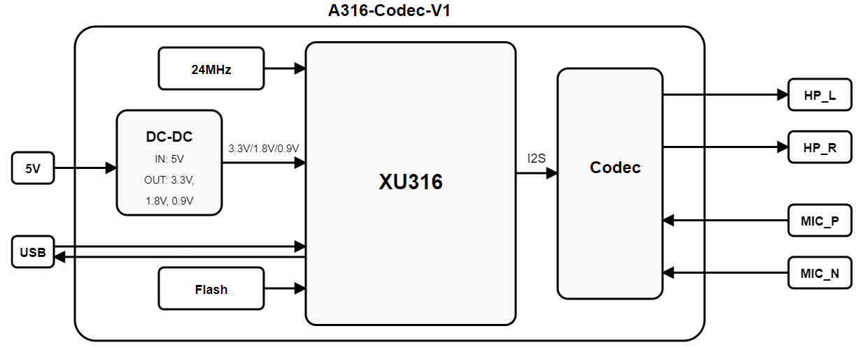
- The module integrates a high-precision DC-DC power circuit that outputs 3.3V, 1.8V, and 0.9V to power the XU316. External input only requires a 5V power supply, significantly simplifying the design complexity of baseboard applications.
- The module supports external single-ended and differential microphone inputs and provides stereo audio output, suitable for various audio capture and playback application scenarios.
- The module is equipped with 16Mbit Flash memory for storing audio firmware and system configuration, supporting firmware upgrade functionality.
- Provides USB 2.0 interface, supports full-speed and high-speed modes, implements USB Audio device functionality, and is compatible with multiple operating systems.
1.2 Product Features
-
USB Interface Features
- USB 2.0 (Full-speed and High-speed modes)
- USB Audio Class 1.0/2.0 support
- USB Device Firmware Upgrade (DFU) functionality
- Asynchronous transfer mode, reduces clock jitter
-
Audio Input/Output Capabilities
- Integrated NAU88L21 high-performance audio codec
- Supports single-ended and differential microphone inputs
- Provides high-quality stereo audio output
- Built-in microphone preamplifier
- Supports multiple audio interface specifications
- 48 KHz/24 bit high-quality audio sampling
-
System Compatibility
- Supports multiple operating systems including Windows, Linux, Android, macOS and iOS
- Plug and play, no additional drivers required (UAC 2.0 compatible systems)
- Suitable for conference systems, gaming headsets, professional recording equipment and other application scenarios
1.3 Product Block Diagram
1.4 Specification Description
| Specification Item | Description |
|---|---|
| Product Name | A316-Codec-V1 |
| Product Description | USB Microphone and Audio Input/Output Module |
| Core Processor | XMOS XU316-1024-QF60BC24 |
| Audio Codec | NAU88L21 High-Performance Codec |
| Package Type | Compatible with SMT and Pin Header |
| Environmental Standard | Complies with RoHS Directive |
1.5 Absolute Maximum Ratings
| Parameter | Minimum | Maximum | Unit |
|---|---|---|---|
| Storage Temperature | -40 | 125 | ℃ |
| Supply Voltage | -0.5 | 5.5 | V |
| ESD Voltage (Human Body Model) TAMB-25℃ | -2 | 2 | KV |
| ESD Voltage (Machine Model) TAMB-25℃ | -500 | 500 | V |
1.6 Normal Operating Conditions
| Function | Minimum | Typical | Maximum | Unit |
|---|---|---|---|---|
| Operating Temperature | 0 | 25 | 70 | ℃ |
| Operating Voltage (Module Input) | 4.75 | 5.0 | 5.25 | V |
1.7 Operating Current
| Operating State | Average | Peak | Unit |
|---|---|---|---|
| Active@5.0V | 100 | 150 | mA |
2. Pin Definition
2.1 Pin Layout
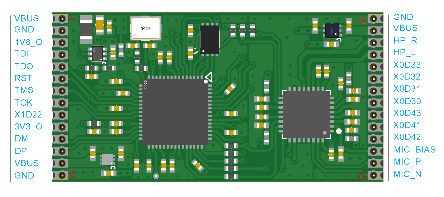
2.2 Pin Description
| Pin Number | Name | Type | Function |
|---|---|---|---|
| 1 | VBUS | P | 5V Power Input |
| 2 | GND | P | Module Ground |
| 3 | 1V8_O | O | 1.8V Power Output (Debug Use Only) |
| 4 | TDI | I | XTAG Debug PIN |
| 5 | TDO | O | XTAG Debug PIN |
| 6 | RST | I | System Reset, Active Low (Internal Pull-up) |
| 7 | TMS | I/O | XTAG Debug PIN |
| 8 | TCK | I | XTAG Debug PIN |
| 9 | X1D22 | I/O | Multi-function GPIO |
| 10 | 3V3_O | O | 3.3V Power Output (Debug Use Only) |
| 11 | DM | I/O | USB Data Negative |
| 12 | DP | I/O | USB Data Positive |
| 13 | VBUS | P | 5V Power Input |
| 14 | GND | P | Module Ground |
| 15 | GND | P | Module Ground |
| 16 | VBUS | P | 5V Power Input |
| 17 | HP_R | O | Headphone Right Channel Output |
| 18 | HP_L | O | Headphone Left Channel Output |
| 19 | X0D33 | I/O | Multi-function GPIO |
| 20 | X0D32 | I/O | Multi-function GPIO |
| 21 | X0D31 | I/O | Multi-function GPIO |
| 22 | X0D30 | I/O | Multi-function GPIO |
| 23 | X0D43 | I/O | Multi-function GPIO |
| 24 | X0D41 | I/O | Multi-function GPIO |
| 25 | X0D42 | I/O | Multi-function GPIO |
| 26 | MIC_BIAS | O | Microphone Bias Voltage Output |
| 27 | MIC_P | I | Microphone Positive Input |
| 28 | MIC_N | I | Microphone Negative Input |
Note: I/O type definitions in the table: I=Input, O=Output, P=Power, I/O=Input/Output
3. Module Dimensions and PCB Footprint
3.1 Module Dimensions
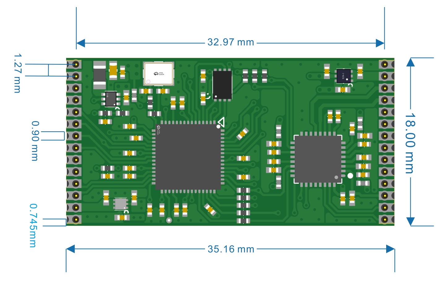
PCB Dimensions: 18.0±0.2(L)X35.16±0.2(W)X1.0±0.1(H) mm
3.2 Module Footprint
4. Typical Application Schematic
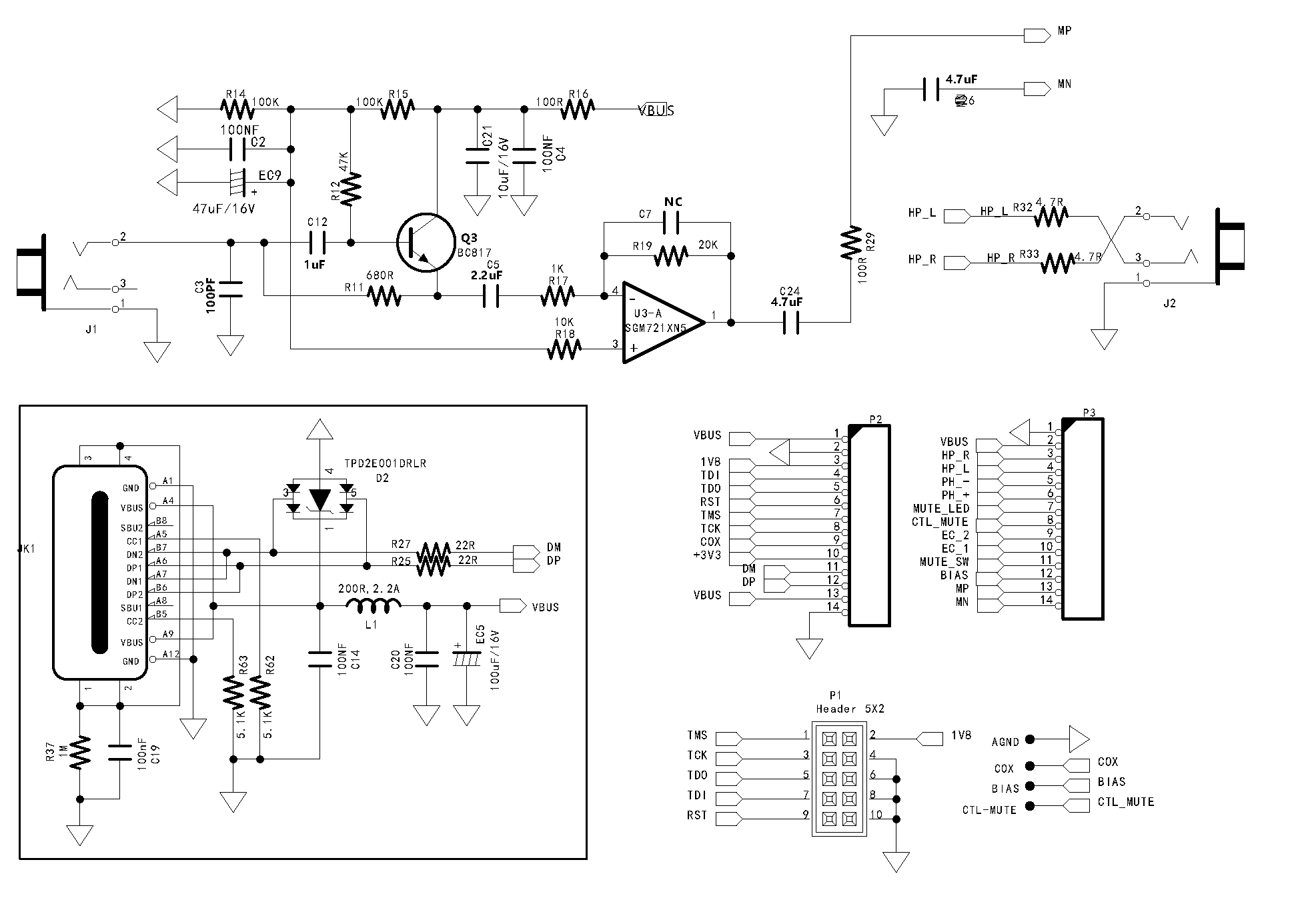
This schematic illustrates the typical connection method for the A316-Codec-V1 module in USB microphone applications. The module connects to a host device (such as a computer or smartphone) through the USB interface, enabling bidirectional digital audio transmission. External input only requires 5V power supply, and the module's internal DC-DC power management circuit automatically converts to the operating voltages required by the XU316 and 88L21. The microphone input port supports connecting single-ended or differential microphones, and the stereo output can connect to headphones. The module's integrated high-performance codec ensures audio quality while simplifying external circuit design.
5. Product Packaging Information
Tray + Outer Box Packaging
6. Recommended Reflow Soldering Temperature Profile
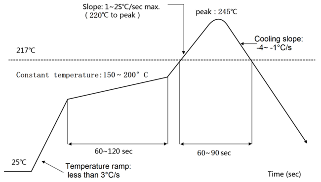
6. Revision History
| Version | Date | Description | Revised by |
|---|---|---|---|
| V1.0 | 2025-05-07 | Initial Release | |


